Low-Voltage Reactive Power Compensation Controller
The low-voltage reactive power compensation controller is designed for low-voltage reactive power compensation systems and is used to provide precise and rapid compensation control for capacitor banks. It utilizes a DSP core chip, supports single-phase and three-phase compensation, and offers flexible parameter setting, fast switching response, and multiple control modes. With RS-485 communication, MODBUS protocol support, and temperature sensing and protection functions, it is suitable for low-voltage compensation systems requiring stable, intelligent, and efficient control performance.
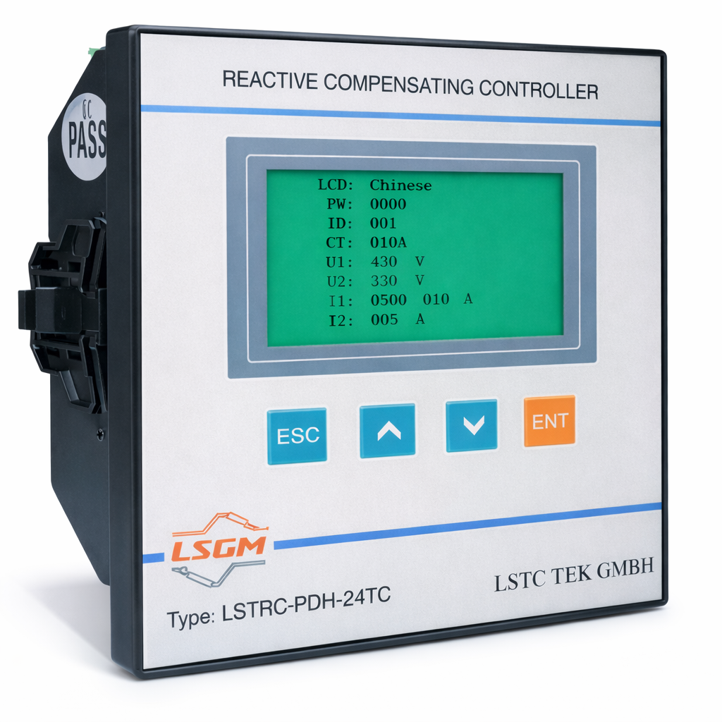
Main Features
Utilizes a DSP core chip to meet more precise and rapid compensation requirements
Ultra-thin design for compact installation
Equipped with a custom LCD screen, offering extensive parameters and flexible operation
Wide voltage power supply, suitable for various environments
Features an RS-485 communication interface, supporting the MODBUS protocol
Single-phase and three-phase compensation with output switching trigger signal <20ms
Allows custom setting of each capacitor’s physical capacitance value
Supports two switching schemes: cyclic (any coding) and linear (first in, first out)
Adjustable compensation speed options: dynamic and static
Temperature sensing and control output function to protect the compensation unit from high-temperature operation
Offers both manual and automatic control modes
Applications
- Low-voltage reactive power compensation systems
- Capacitor bank control applications
- Single-phase and three-phase compensation control
Technical Data
Operating Environment
Altitude: ≤2500 meters
Ambient Temperature: -20℃ to +70℃
Relative Humidity: 20% to 90% at 40℃
Atmospheric Pressure: 79.5 KPa to 106 KPa
Environmental Conditions
Surrounding media should be free from explosive hazards, gases that could damage insulation or corrode metal, conductive dust; the installation site should not be subject to significant vibration and should be protected from wind and snow.Basic Parameters
Power Supply Voltage: AC220V ±20%, 50Hz
Sampling Voltage: AC380V, 220V
Sampling Current: 0 to 5A
Power Consumption: ≤12W
Measurement Accuracy
Voltage: ±0.5%
Current: ±0.5%
Power Factor: ±1.0%
Reactive Power: ±1.0%Control Parameters
Number of Capacitor Circuits: 1 to 12/18/24 circuits (temperature control and alarm output optional)
Current Transformation Ratio: 1 to 1000 (e.g., set to 100 for 500/5 CT)
Overvoltage Setting: 400V to 480V / 230V to 280V, step 1V
Undervoltage Setting: 300V to 360V / 180V to 210V, step 1V
Harmonic Voltage Setting: 0 to 25%
Harmonic Current Setting: 0 to 100%
Target Power Factor: 0.85 to 1.0
Switching Threshold: 0.5 to 1.2, step 0.1
Switching Delay: 0.02s to 600s
Discharge Delay: 0s to 300s
Switching Mode: 0 (cyclic), 1 (linear)
Capacitor Capacitance Value: 0 to 200 Kvar, step 1
Sensitivity: ≤100mA
Output Contact: Each circuit DC12V/30mA or AC250V/5A